路由器设置静态路由的方法(静态路由及默认路由实战)
1、实验目的
掌握如下技能:
(1) 路由表的概念
(2) ip route 命令的使用
(3) 根据需求正确配置静态路由
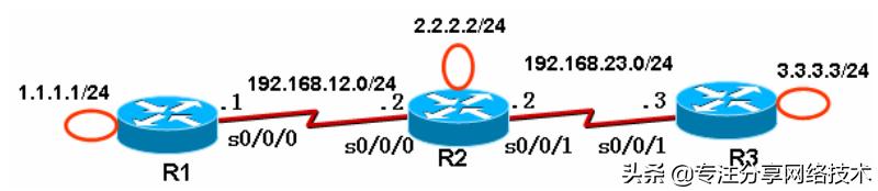
2. 实验拓扑
3. 实验步骤
我们要使得 1.1.1.0/24、2.2.2.0/24、3.3.3.0/24 网络之间能够互相通信。
(1) 步骤 1:在各路由器上配置 IP 地址、保证直连链路的连通性
R1(config)# int loopback0
R1(config-if)# ip address 1.1.1.1 255.255.255.0
R1(config)# int s0/0/0
R1(config-if)# ip address 192.168.12.1 255.255.255.0
R1(config-if)# no shutdown
R2(config)# int loopback0
R2(config-if)# ip address 2.2.2.2 255.255.255.0
R2(config)# int s0/0/0
R2(config-if)# clock rate 128000
R2(config-if)# ip address 192.168.12.2 255.255.255.0
R2(config-if)# no shutdown
R2(config)# int s0/0/1
R2(config-if)# clock rate 128000
R2(config-if)# ip address 192.168.23.2 255.255.255.0
R2(config-if)# no shutdown
R3(config)# int loopback0
R3(config-if)# ip address 3.3.3.3 255.255.255.0
R3(config)# int s0/0/1
R3(config-if)# ip address 192.168.23.3 255.255.255.0
R3(config-if)# no shutdown
(2) 步骤 2:R1 上配置静态路由
R1(config)# ip route 2.2.2.0 255.255.255.0 s0/0/0
//下一跳为接口形式,s0/0/0 是点对点的链路,注意应该是 R1 上的 s0/0/0 接口
R1(config)# ip route 3.3.3.0 255.255.255.0 192.168.12.2
//下一跳为 IP 地址形式,192.168.12.2 是 R2 上的 IP 地址
(3) 步骤 3:R2 上配置静态路由
R2(config)# ip route 1.1.1.0 255.255.255.0 s0/0/0
R2(config)# ip route 3.3.3.0 255.255.255.0 s0/0/1
(4) 步骤 4:R3 上配置静态路由
R3(config)# ip route 1.1.1.0 255.255.255.0 s0/0/1
R3(config)# ip route 2.2.2.0 255.255.255.0 s0/0/1
4. 实验调试
(1) 在 R1、R2、R3 上查看路由表
R1# show ip route
Codes: C - connected, S - static, R - RIP, M - mobile, B - BGP
D - EIGRP, EX - EIGRP external, O - OSPF, IA - OSPF inter area
N1 - OSPF NSSA external type 1, N2 - OSPF NSSA external type 2
E1 - OSPF external type 1, E2 - OSPF external type 2
i - IS-IS, su - IS-IS summary, L1 - IS-IS level-1, L2 - IS-IS level-2
ia - IS-IS inter area, * - candidate default, U - per-user static route
o - ODR, P - periodic downloaded static route
Gateway of last resort is not set
C 192.168.12.0/24 is directly connected, Serial0/0/0
1.0.0.0/24 is subnetted, 1 subnets
C 1.1.1.0 is directly connected, Loopback0
2.0.0.0/24 is subnetted, 1 subnets
S 2.2.2.0 is directly connected, Serial0/0/0
3.0.0.0/24 is subnetted, 1 subnets
S 3.3.3.0 [1/0] via 192.168.12.2
2.0.0.0/24 is subnetted, 1 subnets
S 2.2.2.0 is directly connected, Serial0/0/0
3.0.0.0/24 is subnetted, 1 subnets
S 3.3.3.0 [1/0] via 192.168.12.2
R2# show ip route
Codes: C - connected, S - static, R - RIP, M - mobile, B - BGP
D - EIGRP, EX - EIGRP external, O - OSPF, IA - OSPF inter area
N1 - OSPF NSSA external type 1, N2 - OSPF NSSA external type 2
E1 - OSPF external type 1, E2 - OSPF external type 2
i - IS-IS, su - IS-IS summary, L1 - IS-IS level-1, L2 - IS-IS level-2
ia - IS-IS inter area, * - candidate default, U - per-user static route
o - ODR, P - periodic downloaded static route
Gateway of last resort is not set
C 192.168.12.0/24 is directly connected, Serial0/0/0
1.0.0.0/24 is subnetted, 1 subnets
S 1.1.1.0 is directly connected, Serial0/0/0
1.0.0.0/24 is subnetted, 1 subnets
S 1.1.1.0 is directly connected, Serial0/0/0
2.0.0.0/24 is subnetted, 1 subnets
C 2.2.2.0 is directly connected, Loopback0
3.0.0.0/24 is subnetted, 1 subnets
S 3.3.3.0 is directly connected, Serial0/0/1
3.0.0.0/24 is subnetted, 1 subnets
S 3.3.3.0 is directly connected, Serial0/0/1
C 192.168.23.0/24 is directly connected, Serial0/0/1
R3# show ip route
Codes: C - connected, S - static, R - RIP, M - mobile, B - BGP
D - EIGRP, EX - EIGRP external, O - OSPF, IA - OSPF inter area
N1 - OSPF NSSA external type 1, N2 - OSPF NSSA external type 2
E1 - OSPF external type 1, E2 - OSPF external type 2
i - IS-IS, su - IS-IS summary, L1 - IS-IS level-1, L2 - IS-IS level-2
ia - IS-IS inter area, * - candidate default, U - per-user static route
o - ODR, P - periodic downloaded static route
Gateway of last resort is not set
1.0.0.0/24 is subnetted, 1 subnets
S 1.1.1.0 is directly connected, Serial0/0/1
2.0.0.0/24 is subnetted, 1 subnets
S 2.2.2.0 is directly connected, Serial0/0/1
1.0.0.0/24 is subnetted, 1 subnets
S 1.1.1.0 is directly connected, Serial0/0/1
2.0.0.0/24 is subnetted, 1 subnets
S 2.2.2.0 is directly connected, Serial0/0/1
3.0.0.0/24 is subnetted, 1 subnets
C 3.3.3.0 is directly connected, Loopback0
C 192.168.23.0/24 is directly connected, Serial0/0/1
(2) 从各路由器的环回口 ping 其他路由器的环回口:
R1# ping
//不带任何参数的 ping 命令,允许我们输入更多的参数
Protocol [ip]:
Target IP address: 2.2.2.2 //目标 IP 地址
Repeat count [5]: //发送的 ping 次数
Datagram size [100]: //ping 包的大小
Timeout in seconds [2]: //超时时间
Extended commands [n]: y //是否进一步扩展命令
Source address or interface: 1.1.1.1 //源 IP 地址
Type of service [0]:
Set DF bit in IP header? [no]:
Validate reply data? [no]:
Data pattern [0xABCD]:
Loose, Strict, Record, Timestamp, Verbose[none]:
Sweep range of sizes [n]:
Type escape sequence to abort.
Sending 5, 100-byte ICMP Echos to 2.2.2.2, timeout is 2 seconds:
Packet sent with a source address of 1.1.1.1
!!!!!
Success rate is 100 percent (5/5), round-trip min/avg/max = 12/14/16 ms
//以上说明从 R1 的 loopback0 可以 ping 通 R2 上的 loopback0。也可以直接使用命令:
R1# ping 2.2.2.2 source loopback 0
Type escape sequence to abort.
Sending 5, 100-byte ICMP Echos to 2.2.2.2, timeout is 2 seconds:
Packet sent with a source address of 1.1.1.1
!!!!!
Success rate is 100 percent (5/5), round-trip min/avg/max = 12/14/16 ms
R2# ping 1.1.1.1 source loopback 0
R2# ping 3.3.3.3 source loopback 0
//从 R2 的 loopback0 应该可以 ping 通 R1 和 R3 的 lopback0 接口。
R3# ping 1.1.1.1 source loopback 0
R3# ping 2.2.2.2 source loopback 0
//从 R3 的 loopback0 也应该可以 ping 通 R1 和 R2 的 lopback0 接口。
【提示】虽然从 R1 的 loopback0 可以 ping 通 R3 的 loopback0,数据需要经过
192.168.23.0/24 网络,但是在 R1 上我们并没有添加 192.168.23.0/24 的路由。路由器转
发数据包完成是根据路由表的,并且数据是一跳一跳地被转发的,就像接力赛似的。从 R1
的loopback0口ping R3的loopback0口时,IP数据包的源IP为1.1.1.1,目的IP为3.3.3.3。
R1 路由器首先查路由表,数据包被发到了 R2;R2 路由器也查路由表(3.3.3.0/24 路由),
数据包被发到了 R3;R3 知道这是直连路由。R3 响应 R1 的数据包进行类似的过程。
(3) 从 R1 上 ping 2.2.2.2、从 R1 上 ping 3.3.3.3
R1# ping 2.2.2.2
Type escape sequence to abort.
Sending 5, 100-byte ICMP Echos to 2.2.2.2, timeout is 2 seconds:
!!!!!
Success rate is 100 percent (5/5), round-trip min/avg/max = 12/14/16 ms
//可以 ping 通。
R1# ping 3.3.3.3
Type escape sequence to abort.
Sending 5, 100-byte ICMP Echos to 3.3.3.3, timeout is 2 seconds:
.....
Success rate is 0 percent (0/5)
//以上无法ping通,原因在于使用ping命令时,如果不指明源接口,则R1路由器使用s0/0/0
接口的 IP 地址(192.168.12.1)作为 IP 数据包的源 IP 地址了。R3 上响应 R1 的数据包时,
数据包是发向 192.168.12.1 的,然而由于 R3 没有 192.168.12.0/24 的路由,数据包无法发
送。即:数据包从 R1 到了 R3 后,无法返回 R1。
5. 静态路由
在实验 1 的基础上进行
(1) 步骤 1:R1、R3 上删除原有静态路由
R1(config)# no ip route 2.2.2.0 255.255.255.0 Serial0/0/0
//要删除路由,在原有命令前面加 no 即可
R1(config)# no ip route 3.3.3.0 255.255.255.0 192.168.12.2
R3(config)# no ip route 1.1.1.0 255.255.255.0 Serial0/0/1
R3(config)# no ip route 2.2.2.0 255.255.255.0 Serial0/0/1
(2) 步骤 2: R1、R3 上配置默认路由
R1(config)# ip route 0.0.0.0 0.0.0.0 s0/0/0
R3(config)# ip route 0.0.0.0 0.0.0.0 s0/0/1
,免责声明:本文仅代表文章作者的个人观点,与本站无关。其原创性、真实性以及文中陈述文字和内容未经本站证实,对本文以及其中全部或者部分内容文字的真实性、完整性和原创性本站不作任何保证或承诺,请读者仅作参考,并自行核实相关内容。文章投诉邮箱:anhduc.ph@yahoo.com